Welcome to Model Railway Techniques. In this article we’re going to give you detailed step by step instructions, with illustrations, on exactly how to build benchwork for your Model Railroad on a budget. Whether you’re a beginner, or a seasoned Model Railroader just looking to expand your knowledge, you’ve come to the right place. Read on below to get started and thank you for visiting our website.
There are many schools of thought on how to build benchwork for your Model Railroad out there, and over the years I have tried many different techniques. They range from the older L-girder design, to a more modern, user friendly approach for beginners utilizing hollow core doors or a single piece of extruded polystyrene foam board.
The method I’m going to share with you today is both strong, light weight, and very affordable and is called the Open Grid Method. One thing I have noticed, both with Model Railroaders themselves, or others giving advice on building benchwork, is that often times the recommendations for lumber sizes are mistakenly way over size.
Trust me, with 40 years plus of experience as both a Model Railroader and a carpenter, the size recommendations I provide you are more than adequate, and you can trust my constructions techniques since I have used them for a very long time with excellent results.
Below is a list of tools you will need for this project, and some quick advice of where to obtain some of them with links if you don’t already have them. The material list at the bottom is for a 3′ x 8′ section of benchwork, the size in the illustrations below that I will be giving step by step instructions for.
Total cost for the materials for this is $75.00, priced on the Home Depot website. Optional additional cost for the 1″ or 2″ thick polystyrene foam board at the end of the article is $36.00 and $51.00 respectively.
- TAPE MEASURE- You can get this at any hardware store, and can even find them at your local Dollar Store or equivelant.
- PENCIL OR PEN-
- CARPENTERS SPEED SQUARE– This is a very handy tool used for marking perfectly straight lines across a board. It has a built-in lip to keep your marks accurate. You can get them at a hardware store, and I have even seen them at my local Dollar Tree occasionally.
- CARPENTERS LEVEL– Available at any hardware store. A 3 foot or 4 foot one is more than adequate, there are even cheaper plastic ones that will do just fine.
- FRAMING SQUARE– An invaluable tool you will find many uses for, get the aluminum variety.
- CORDLESS DRILL WITH A #2 PHILLIPS HEAD BIT AND DRIVER ATTACHMENT– A must have, available at hardware stores or even online. For our purposes you don’t need a fancy one, so shop around before buying. The driver attachment will make starting screws much easier and save your fingers from pinching or metal slivers.
- SAW, POWER OR HAND STYLE- You can use a handsaw, it is a bit more work though. Another alternative is to bring your list of lumber lengths to Home Depot or Lowes and they will make the cuts for you. If you are considering buying a power saw there are affordable options for these, and only need to have a 4-1/2″ blade for our purposes. As with any power tool, please follow the directions of the manufacturer and observe all safety precautions.
- OPTIONAL- Spade drill bit, 1/2″ or 5/8″ for pre-drilling holes for future wiring.
- MATERIAL LIST-
- 1 X 3 X 96″- (8)
- 2 X2 X 96″- (2)
- 1 lb Box of 1-1/4″ Drywall Screws- (1)
So without further delay, let’s build some benchwork for your Model Railroad!
STEP 1: DETERMINE YOUR SIZE AND GATHER YOUR TOOLS AND MATERIAL LIST
While I wrote this article on a specific size of 3′ x 8′ your actual needs and size may be different. When deciding on what size to build your Model Railroad benchwork there are a few key factors to remember:
- OVERALL SIZE AND ACCESIBILTY- It is important to consider this both from a standpoint of the actual building phase, to the near completion phase and maintenance requirements. Most people can only reach comfortably about 24″. If you can’t provide access to the backside of your layout of at least 16″ then it is recommended you keep the width to 24″ or less.
- There are ways around this if you plan in advance. For example, when I built my current 3’x13′ layout I had no access to the back side. To work around this issue, I initially set the layout height low, around 36″, and completed and tested all of the track work in the back first. I was able to use the front 2′ of the layout to rest my arms on to limit straining of my back and fatigue.
- I also used this same method as I began scenery, working from the back first so as not to damage elements in the front. While not ideal, it was necessary for me since I wanted minimum 15″ radius curves for reliable operation. This method may or may not work in your situation.
- PERMANENT, SEMI-PERMANENT, OR EASILY RELOCATED- Another consideration is the actual space you are going to build your Model Railroad in. If you have a permanent space and no worries about relocating, then the back side can be attached directly to the walls and the rear legs can be omitted. If you are unsure of the permanence, you can still attach the layout to the wall, but you must consider the overall size of the benchwork in case you ever need to relocate it.
- Weight is not as much of an issue as maneuverability, my 3′ x 13′ layout was light enough to be carried by myself. Corner obstructions and doorways pretty much limit the size of the layout or sections to around 3’x8′. For the last option of Easily Relocated, then the 3’x8′ four leg free standing design I will describe in detail below should suit you, but again, consider difficulties in moving out of its current location and into a new area.
STEP 2: CHOOSING YOUR LUMBER
When buying the lumber for your project there are a few things to keep in mind. This benchwork is built using 1x3x8′ kiln dried lumber. It is important to use the kiln dried variety, since this process greatly reduces the chances of warping later on, which can cause unwanted variations in the benchwork.
Another consideration when purchasing your lumber is to look for the pieces with the fewest number of knots in them, as these are natural areas where further distortion can occur. Small knots are acceptable but try to avoid any knots greater than 1/3 the width of the boards. (1″ or less)
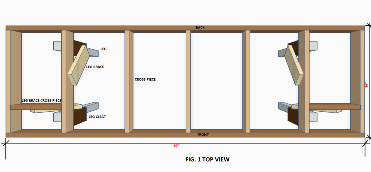
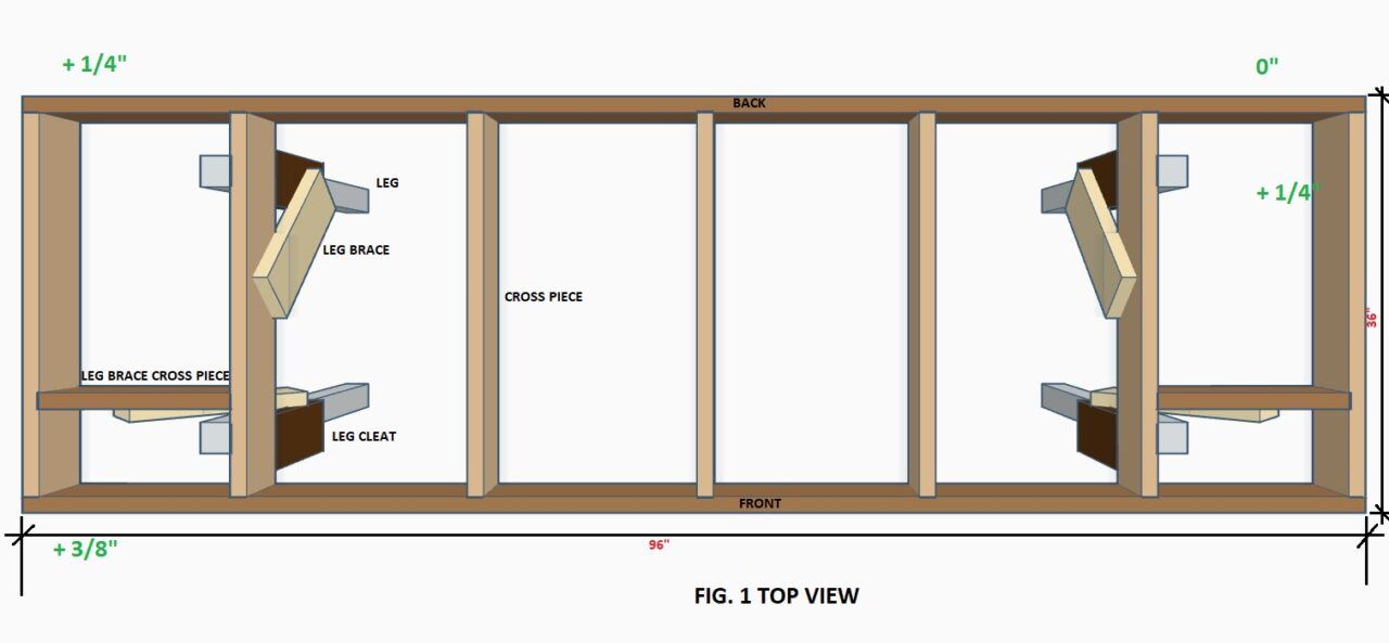
The last thing to look for is straightness of the lumber. For your longest lengths (front and back, reference Fig. 1 below) look for the straightest ones possible. Particularly the ‘crown’ of the lumber. This can be viewed by sighting along the top and bottom edges of the lumber with your eyes, most often you will see a slight, or in extreme cases, arc to the lumber.
Choose the ones with least, or no perceptible crown. For shorter pieces like the cross pieces, braces, and leg cleats, this is not as important since when you cut the pieces the overall crown is effectively reduced and not an issue. (reference Fig. 1)
STEP 3: BULDING THE INITIAL FRAME
So now that you have decided on an area to build your Model Railroad, and you have gathered the necessary tools and materials, let’s move into the actual building process. I recommend you look through the various 3D renderings to familiarize yourself first with some of the parts I will be referencing in this article.
Also, I highly recommend the use of the drywall screws in the material list, they are both easy to install, and don’t require pre-drilling of the wood which greatly speeds up the process. Even for a first timer, or those with less carpentry skills, you should be able to complete this in about a day or less. You will need a helper when it comes time to flip your benchwork over, or attach to a wall, this will make it much easier.
The first step is to measure and cut your front and back pieces to the length you want. After that, determine on the spacing of your cross pieces. (Reference Fig, 1 above) and lay your front and back pieces side by side for the marking process.
The spacing of the cross pieces should be roughly equal, with a suggested spacing of no more than 24″, with an ideal spacing of around 16″ for the greatest strength. You can easily determine this with the following method and a calculator:
For lengths around 7 to 8 feet, take the total inches, 84″ or 96″ in this example, and divide by 6. This will give you a result around 16″, ignore the decimals as this does not need to be exact. You will notice that the 96″ long example will come out to 16″ exactly, and the 84″ long example will come out to 14″.
To increase the spacing repeat the process, but this time divide by 5. The result will be 19″ and 16″ this time. You can use this easy method on any length, increasing or decreasing the dividing number until you get close to the spacing you want.
Once you have the spacing cut your cross pieces to length. Try to avoid making cuts where there are larger knots, it makes driving the screws more difficult and splitting of the ends is more likely to occur. Now that you have your cross pieces cut, mark them out on the front and back pieces using your speed square and the following process.
Set the front and back pieces on edge side by side making sure the ends are even. Using your tape measure, mark out the spacing and draw a straight line across both boards. Don’t worry if the last one is off by an inch or two, we’re not building fine furniture here!
Now, using your screw gun with a #2 phillips bit and driver attachment, attach each cross piece to the front and back pieces using two screws on each end, (Reference Fig. 2, below, red dots indicate screws). Do this on a suitable flat surface and make sure to keep the tops of each piece flush with each other as you go. Keep your screws about 1/2″ down from the top and bottom of the front and back boards so you do not split out the ends of your cross pieces.
You will find that the drywall screw will start very easily thanks to their very pointed ends and will flush out nicely with the wood giving you a solid joint. The driver adjustment will help to keep the screw located on the bit and prevent slippage. At this point you will have a completed rectangular grid like in Fig. 1 above. Congratulations you’re almost there!
STEP 4: ATTACHING THE LEGS
You should be very proud of yourself by this point! You have learned how to select your lumber, measure and cut the pieces, and assemble a basic grid frame. Now on to attaching the legs for your Model Railroad. It should be noted that if you are planning to attach the backside of your layout to a wall, then the back leg assemblies can be omitted.
The configurations of the braces as shown will adequately stabilize your new layout both side to side and front to back if you are building the free-standing version in this article. I purposely keep the front leg braces outward so that there is maximum access to the underside of the layout both for construction purposes, and for storage area.
Model Railroaders’ tend to accumulate a lot of various items during the process, and the area under the layout is both convenient and practical for storage.
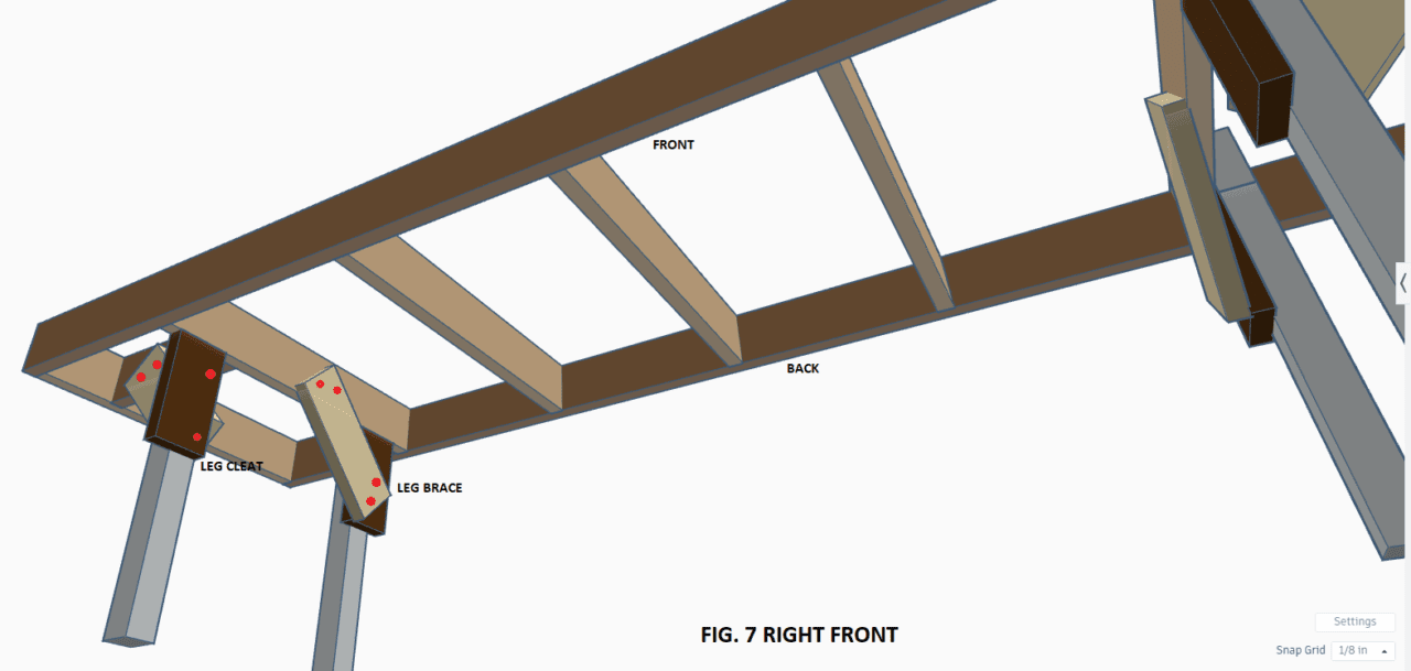
Please reference the photos below carefully to get an understanding of the leg assemblies and their components. There are a few key items to keep in mind as you go through this process. Below I touch on the subject of layout height also, I preparation of determining the length of the legs.
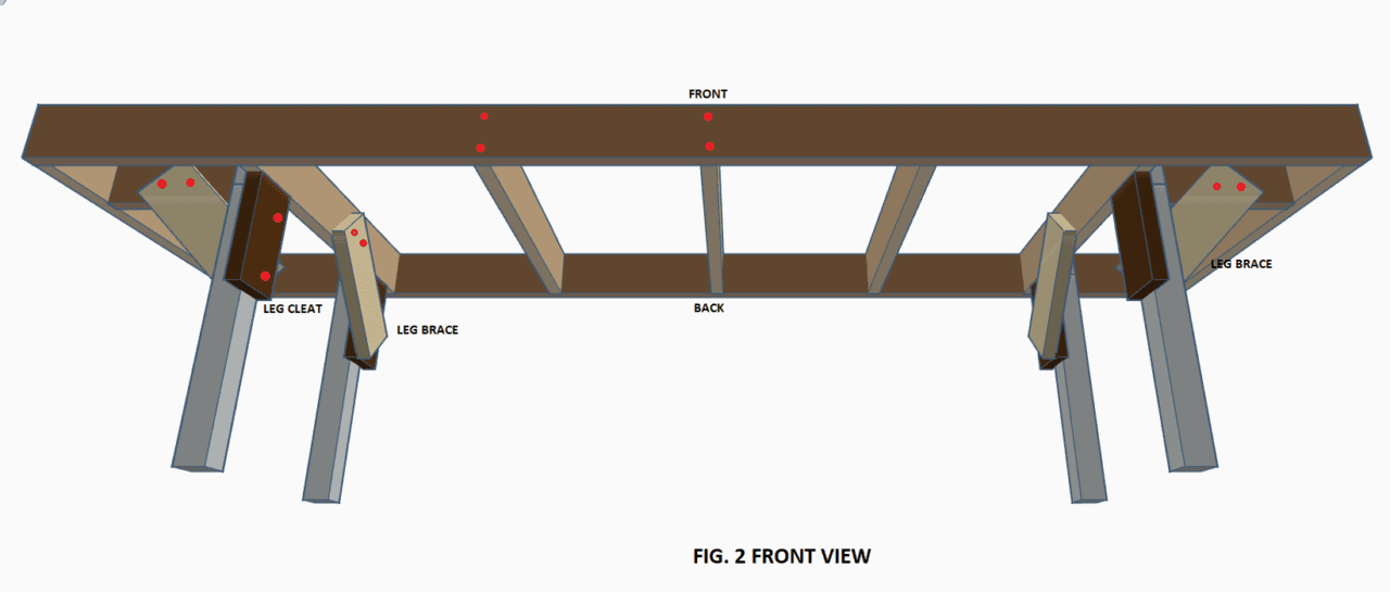
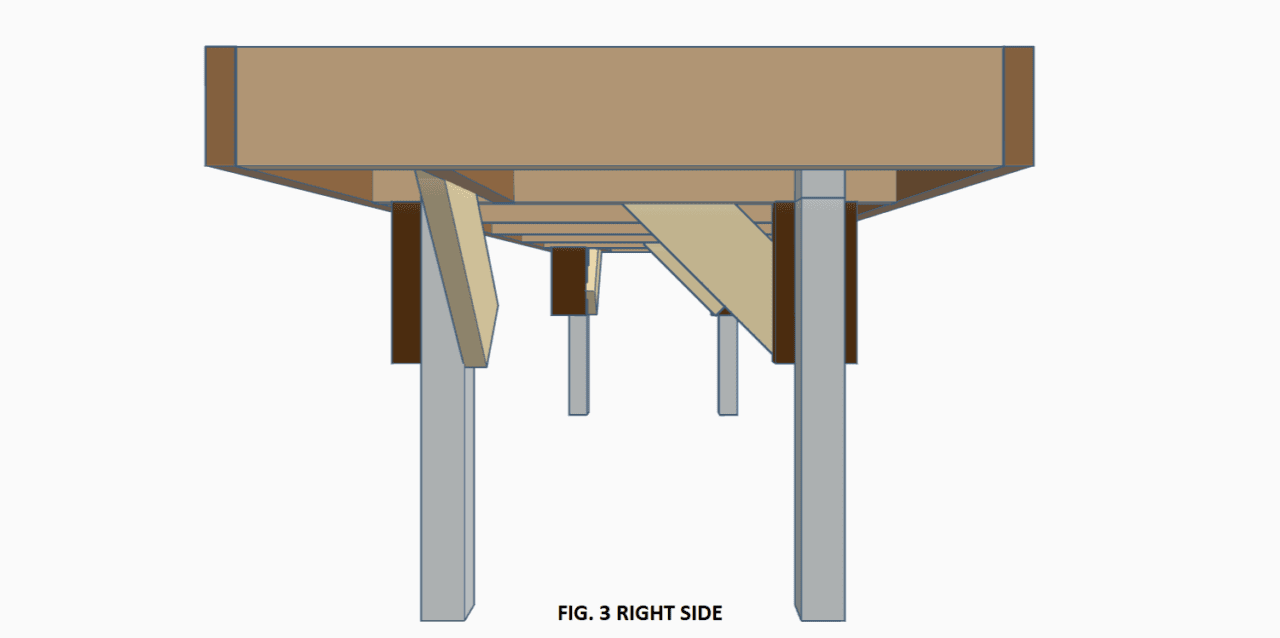
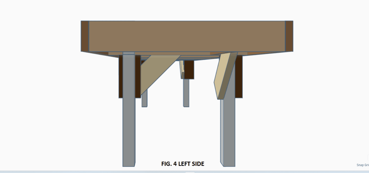
By studying the images above, (Figs. 2-6) you can familiarize yourself with the various components that make up the leg assemblies:
- LEGS- Self explanatory, these support your layout. The length will determine the overall height of your layout. There are many opinions on this, below are my takes on the various height ranges.
- Approximate layout height of 36″- Offers ease of construction since this height is comfortable enough for the average person to lean across. It is also more child friendly height for viewing. The downside is that you have a ‘birds-eye’ view of the layout, and generally see every element at once. If seated, it offers a more realistic scene perspective, but you are bound to a single viewing location.
- Approximate layout height of 45″- This height is closer to a realistic viewing height without a chair. Construction is a bit more challenging since now you’re reaching further and not able to lean at your hips. This height is also considered high for children since it is near their eye level, and they cannot see items in the background.
- Layout height of 50″ or more- This gives the most realistic perspective of the layout itself and has advantages of being able to use foreground view blocks to hide background items or reveal them as one moves along the layout. This height can really make a layout seem much larger than it is, and also shallow benchwork such as shelf railroad designs seem deeper than they really are. The disadvantage is that for any background construction the use of small step ladders or other elevated means is required. Many layouts this height are tailorized for their owners who truly enjoy this true trackside perspective.
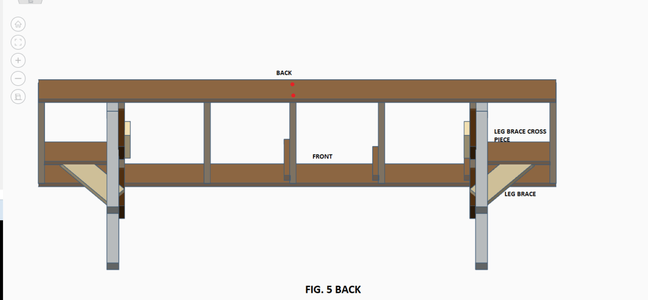
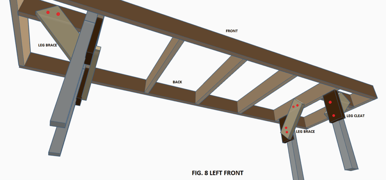
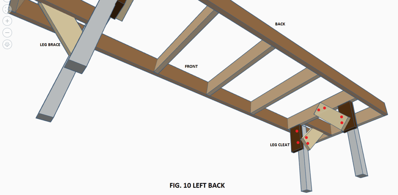
- LEG BRACES- These serve the purpose of stabilizing your layout and minimize side to side and front to back movement in the event the layout is accidently bumped.
- LEG CLEATS- These are an added strengthening measure to support the layout, and also allow easy adjustment when it is time to level the layout when the backside is mounted to a wall.
To begin with attaching the legs first cut your legs to the desired length using the guidelines above. If you find that your chosen layout height doesn’t work, you can re-adjust them later either by cutting them shorter or getting longer pieces of 2×2 to make it higher. As a starting point, for an average person’s height of 5′-9″, I would suggest 37″ legs.
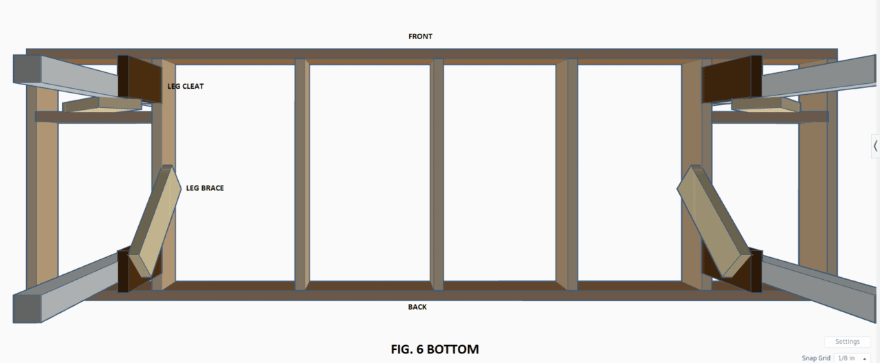
After you have cut them to this length, measure down 2-1/2″ on each one and mark a straight line across one side using your speed square. Next, attach a leg cleat (Reference Fig.6) to each one using two screws (as seen in Fig. 2 above, or Fig. 7 and 8 below) make sure they are even with the lines you marked. the length of each cleat should be about 16″ to allow for an adequate angle for the leg braces to attach to later.
Two of the cleats should be centered on the 2×2 legs, and the other two should be flush with one side, making sure you have a left and right version of this. (mirrored) Again, reference Fig. 6 above or Fig. 7 and 8 below. When you attach the cleats, keep each set of screws slightly off-center so you don’t cause the cleat to split down the center. Space the screws about 2″ from each end of the cleat.
The next step is to attach each leg using one screw to the main cross pieces as seen above. I recommend that you place the legs 6″ in from the edge of the front and back pieces. This will minimize the possibility of yours, or someone else’s toes from accidentally kicking the legs.
The cleats should rest snuggly on the cross member and will provide an initial square setting relevant to your framework. Center each screw on the leg and cross piece, screwing from the cross piece into each leg. Also make sure that the two front legs, the ones with the cleats flush to the legs, are positioned correctly. The flush side of each should be facing towards the center of your frame. Reference Fig. 6 below to make sure you have these aligned correctly.
STEP 5: ATTACHING THE DIAGONAL LEG BRACES
The final step in attaching the legs is to add the two front leg brace cross pieces and add the four diagonal braces. Begin by measuring the distance between the cross piece and end piece at each front leg location. Cut these to length, then attach them to each cross piece and end piece using two screws on each end just as you did when you built the initial grid framework. Important: You must leave 3/4″ between the legs and the leg brace cross piece to allow the diagonal brace to align properly, (Reference Fig. 6 above).
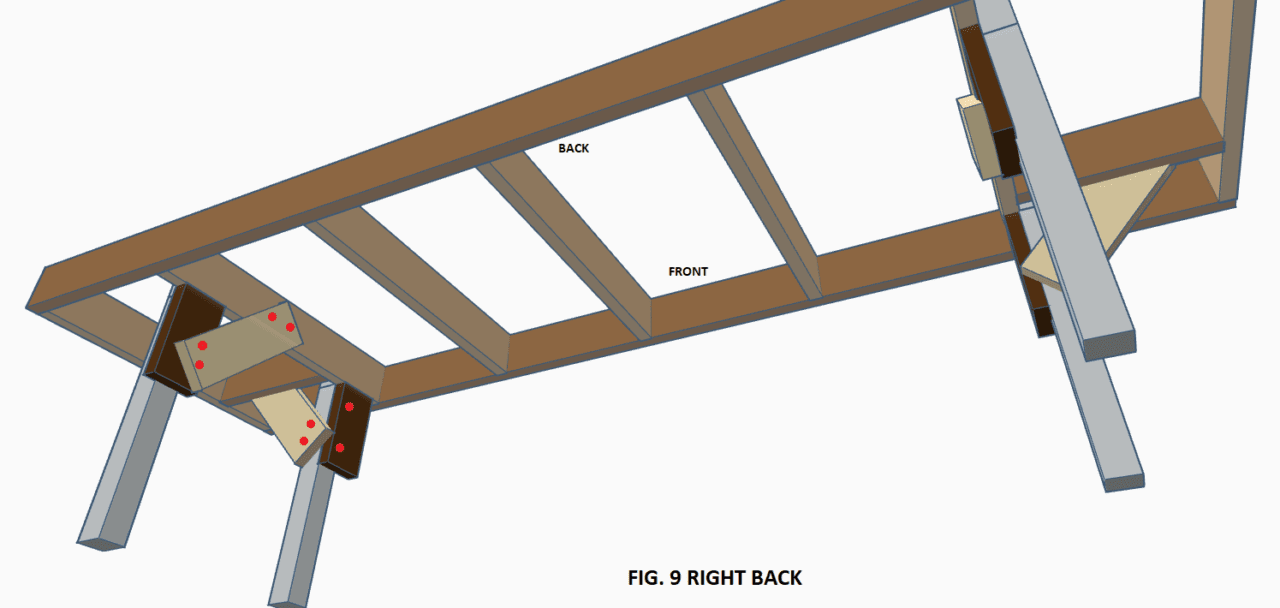
Once you have the two leg brace cross pieces installed, measure from the leg brace cross piece from the end that is to the outside, to the bottom of the leg cleat. Figs. 5, 9, and 10 below illustrates this. Cut these to length, they should be the same length if your legs are sitting pretty straight.
Once these are cut, position each one as shown above, and attach only the end going to the leg brace cross brace with two screws. Now take your framing square and stand it up with the longer leg facing upwards, and the shorter leg lying across the leg brace cross piece. The corner of the framing square should be even with end of the leg brace cross piece.
This will allow you to set the leg at a 90-degree angle to the framework. You may need a hand at this point to hold the framing square in this location as you align the leg with the edge of the framing squares long side. Once you have it aligned satisfactorily, squeeze the leg and diagonal brace together to hold them in place and mark the end of the diagonal brace on either side of the leg for reference.
Now align your marks and install two screws into each leg. Repeat this process for the other three legs, omitting the installation of the leg brace cross pieces for the rear legs since those two diagonal braces attach directly to the main cross piece. As the final step in installing the legs and braces, install a second screw into each leg at the top, this will add a bit more rigidity to the whole assembly.
Now is also the time to pre-drill for future wiring. Drilling the holes keeps all the wires neatly above the bottom of the benchwork so they don’t get snagged or damaged. At a minimum, drill two holes, centered top to bottom, in each cross piece about 8″ in from the ends. They don’t have to be in a straight line, so just use your eye to judge.
Some people like to drill in the center also for a total of three sets of holes in each cross piece, the choice is yours, and these holes won’t affect the strength if you keep them at 1/2″ or 5/8″ in diameter per the optional tool list at the beginning of the article.
Attaching the legs is by far the most difficult part of this whole process, but if you followed along with the text and referenced the pictures you should have no problems.
You’ve also gained some valuable knowledge in the use of some very simple tools that aid you in building, primarily the use of the speed square and framing square for making sure your construction and cuts are at 90-degree angles, the foundation of any construction techniques.
At this point you can flip your assembly over and you will have a great foundation for your Model Railroad, congratulations!
STEP 6: MINOR ADJUSTMENTS AND LOOKING AHEAD
The final minor adjustments needed once you have your benchwork in place is to level your layout. Assuring that it is level is an important step that you shouldn’t skip.
the process is simple: Place your level on the back side first and read the center vile, the bubble should be in between the two marks. If it’s not, raise one end or the other of the level until it is, and make a note either on paper or the layout itself which corner needs to go up, and by how much.
Try to be fairly accurate with your notes. for example, wright +1/4″ on the appropriate corner. The other corner you will designate as “0”, or your starting point for the actual levelling process. Now do each side, noting again which corner needs to go up, and writing the measurement down.
At this point compare the notes you have with one another. you should have three fractions written down similar to the picture below. Starting with the corner marked “0” add the fraction, if any, from that corresponding side. In the example below you would be adding 1/4″ meaning this corner now has to go up 1/4″.
You then simply add the 1/4″ to the other two measurements (1/4″+1/4″=1/2″) (1/4″+3/8″=5/8″) and raise the corners with shims under the legs accordingly. It is much easier to raise than lower so use this method.
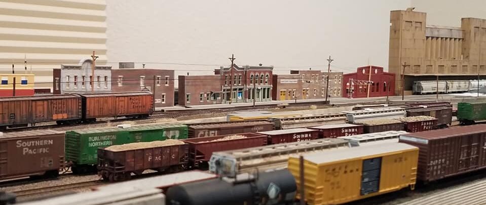
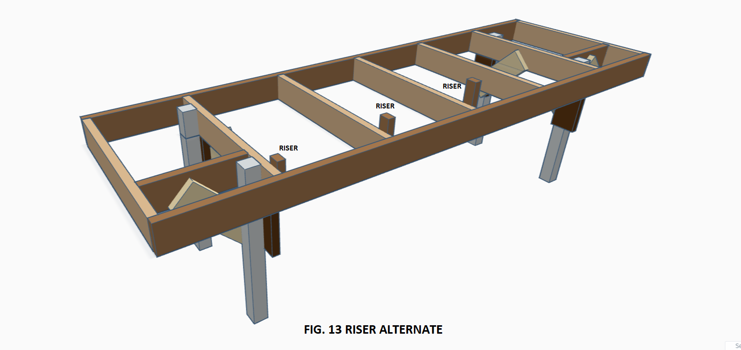
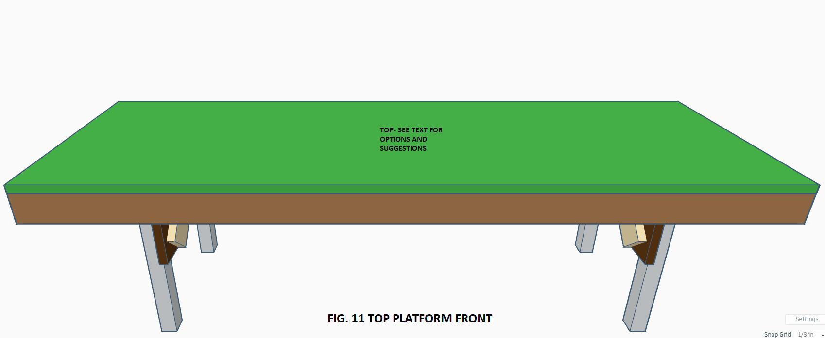
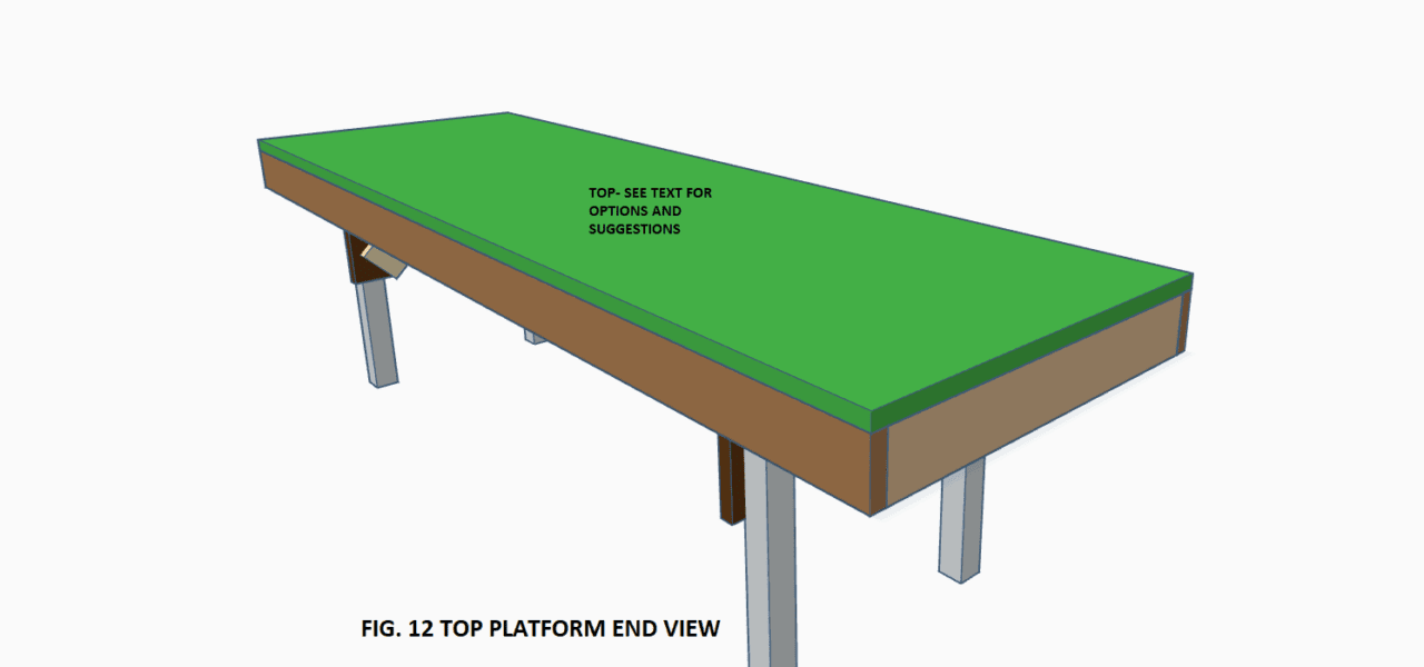
Before I conclude this article, I thought I would share a few more images with you below. At this point you have the open grid benchwork, but still no place to lay track or build scenery. Looking ahead, if you are experienced in Model Railroading, you probably have an idea of what your next steps will be.
But for the beginner, you’re most likely still researching. You can read the article here for some tips. Below are two typical methods that build off the open grid benchwork to get your imagination going with the possibilities. Extruded polystyrene foam board, and risers.
Both have advantages and disadvantages that we will be sharing in a future article. I hope you found this article thorough and informative and take the steps towards building your own benchwork for your Model Railroad with very little investment. Thank you for visiting Model Railway Techniques, James.


RELATED ARTICLES:
Designing Your Model Railroad: Basic Design Ideas For The Small To Medium Sized Model Railroad
N SCALE TRACK PRODUCTS-THE MOST POPULAR N SCALE MODEL RAILROAD TRACK AVAILABLE.
If you enjoyed this post, please share and leave your comments below. Click the subscribe button in the bottom right corner to receive automatic updates of new posts. Your email is confidential and will NOT be shared or redistributed.
James, Model Railway Techniques.com
Last Updated on 2 years ago by James from Model Railway Techniques
Hello! I just finished reading your article on How To Build Affordable Model Railroad Benchwork-Open Grid Method. Keep in mind I know absolutely zip nada about model train stuff as a subject. However, I must say I quite enjoyed your article overall! You offered a materials list for the materials you will need to build a model train benchwork setup, you offered very detailed steps on how to go about the process of actually building that benchwork setup.
And You offered very detailed and informative diagrams/ photos of how this all should be done or could be done depending on what uses you have for your model railroad benchwork. For those like me who have honestly 0 experience with carpentry, I would think this might be something I would be looking for if I was a beginner trying to build an affordable model railroad benchwork.
The only time I’ve ever encountered a model train setup was actually on a job with my dad. We went to someone’s home to do some home repairs together and the gentleman had I’d say quite a massive interest in model trains, and he had his entire basement dedicated to a model train railroad. I had never seen this before! And in such a large capacity too. I could see he had put a ton of work into the details of this.
He talked to my dad for an hour about his interest in model trains. Unfortunately, he was looking for someone who might take this same interest. He had tried to get his own children into it as much as he was, but, they had no interest sadly. As he was getting older, he was looking for someone to pass his railroad on to in the end. He told us he had recently been diagnosed with a terminal illness and wanted his trains and railroad to go to someone who would put them to good use.
Honestly, this particular interest is not one you say too often anymore these days. In a way, it’s one of those arts/ crafts that’s slowly dying out. It was quite a beautiful sight to see though! And how he so loved to delight his guests with his huge indoor basement railroad. It was a very beautiful railroad and well-built too. I could tell he had put hours, maybe even years into maintaining, and designing such a huge display of his craft. Quite an amazing piece of art really.
Overall, I think you did a great job of explaining how to build one of your own railroad benchwork for model trains.
I really enjoyed your article! Thank you for teaching me something new! It was an excellent read. 🙂
Thanks Cal. Coming from someone who has no prior knowledge of building a layout or Model Railroading in general, I really appreciate the comments above. it was my goal to make the article as informative as possible so anyone would feel confident in their ability to do it themselves. I enjoyed your story about the gentleman with the basement empire, I really hope he found someone that appreciated the hobby as much as himself and was able to pass his trains along to them. Thanks you for stopping by Model Railway Techniques, James.
Hey thank you for this post
Though I am unaware of the different techniques of how railways function however trains as a vehicle is something which interests me therefore reading this gave me a great insight into how railway benchwork works. This step by step guide is clear and easy to understand for newbies or those who are an exert in this system. It was easy to follow along, and I like how the materials and other resources were mentioned thoughtfully.
Thanks again and have a great day!
Thank you for the comment, Sariyah. Making it clear and understandable, while also giving detailed information, was the main objective of this article. Often times articles of this nature really don’t go into enough detail to give the reader enough confidence to actually give it a try, or key points are left out which leads to disappointment or frustration. I’m really glad you enjoyed the article, James, Model Railway Techniques.
This is a very informative article James on how to build an affordable model railroad benchwork and I appreciate the experience you impart regarding the varying ways to build such a structure.
The list of necessary tools that you have listed will be extremely beneficial to others so they don’t get involved in a project without knowing beforehand what they will need to accomplish the job. I think for this project the carpenter’s square would be especially crucial.
I have never heard of kiln dried lumber before but am glad to know that it will not warp like other forms of lumber or wood may.
I think it is also important not only that you have designed the framework with braces but explain the purpose for their inclusion. Is it possible the weight of the bench will necessitate the inclusion of more braces?
Hi Joseph, thanks for stopping in and leaving a comment. The braces as described in the article are more than enough to support and stabilize a layout of this size. If the layout is attached to a wall, then the diagonal braces can be omitted entirely since there is no chance of lateral movement. When I build my own benchwork in larger spaces, I usually will space the legs out about five feet. The total weight of that entire 3’x8′ section of benchwork is probably only 35 lbs at best, so you can reason how you really don’t need to overbuild the frame and supports, uselessly wasting money. James, Model Railway Techniques.
This is a very helpful step-by-step guide on how to build an open grid benchwork for model railroads. The list of materials and tools that will be required for the project, means one can make sure you have all the tools before you embark on building the benchwork.
You mention that you are a carpenter. So how easy would it be for somebody that doesn’t have carpentry experience to build this benchwork? The photographs and diagrams are really useful to visualise the end result, but I am just wondering if it would be better for a carpenter to be building the benchwork? Thank you.
Thank you for the comment and question Line. Honestly, you don’t have to be a carpenter to build the benchwork described in the article. The methods and techniques used are quite simp[le. I referenced my carpentry background simply as a re-assurance that the size selection of the lumber used is more than adequate. Often times this lumber is unnecessarily oversized, resulting in un-needed extra cost. We appreciate the comments, thanks for visiting Model Railway Techniques, James.
Thanks for your informative post on building a model railway benchwork.
You can clearly see that you are highly versed and experienced in building techniques for this niche, as your explanations and attention to detail is excellent.
The clear, step by step approach you have provided, with excellent images is very helpful and easy to follow.
I can see that you have also recommended your future article to finish the job with a suitable surface for the railway. I was really surprised at how cheap this was for the materials to do the job.
What would these cost if you were to purchase these fully completed? I would imagine you can save a lot of money for people if they follow your blog.
Well done!
Thank you, Dale, we’re happy you found the article well written and informative There are sites that offer pre-built, or custom style services for this type of benchwork, and the costs for these services can easily triple or quadruple the cost of the basic framework described in the article. There are also ‘professional’ layout builders that will build a ‘complete’ Model Railroad for a considerable amount of money. There are long waiting periods for this however, and then the completed layout needs to be transported and installed. In our opinion that is not a hobby, but a purchase of convenience. our site is dedicated to the hobby itself, and the variety of skills you can gain from it by actually building all of the components involved. We do not promote, and in fact discourage seeking out ‘professional’ services for Model Railroading unless absolutely necessary, such as custom paint jobs on locomotives, as this removes the personal involvement of the hobby of Model Railroading. We thank you again for your comment and questions.
James, Model Railway Techniques.
Your title is very technical and informative. You have described every detail of building a railroad. The size and tools that might be needed all are mentioned here, I respect all your hard work. I will definitely share this informative post with others. Thank you for sharing this post with us. Way to go.
Thanks Liam, we’re glad you found the article informative and interesting. We strive to make sure that all of our articles are presented in a way that it is truly useful to our readers. We appreciate the shares also. Thank you for visiting Model Railway Techniques, James.